进度计划表.doc

应急灯外壳注塑模具设计【8张CAD图纸和说明书】

收藏

资源目录
跳过导航链接。
应急灯外壳注塑模具设计【8张CAD图纸和说明书】.rar
进度计划表.doc---(点击预览)
说明书.doc---(点击预览)
翻译译文.doc---(点击预览)
翻译原文改.pdf---(点击预览)
毕业设计中期检查表.doc---(点击预览)
毕业设计(论文)开题报告.doc---(点击预览)
应急灯外壳注塑模具设计任务书.doc---(点击预览)
CAXA图纸
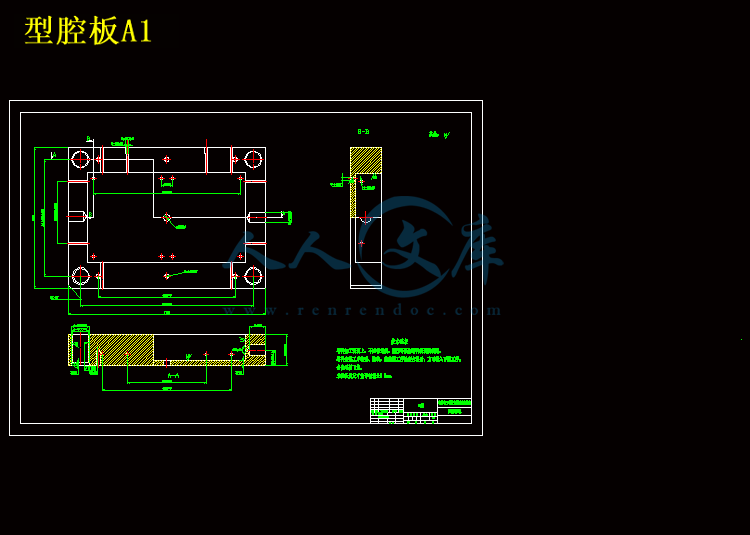
型腔板A1.exb
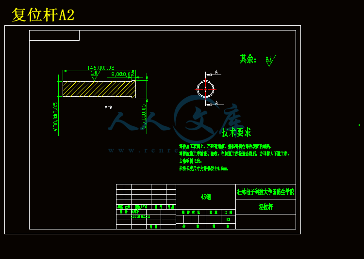
复位杆A2.exb
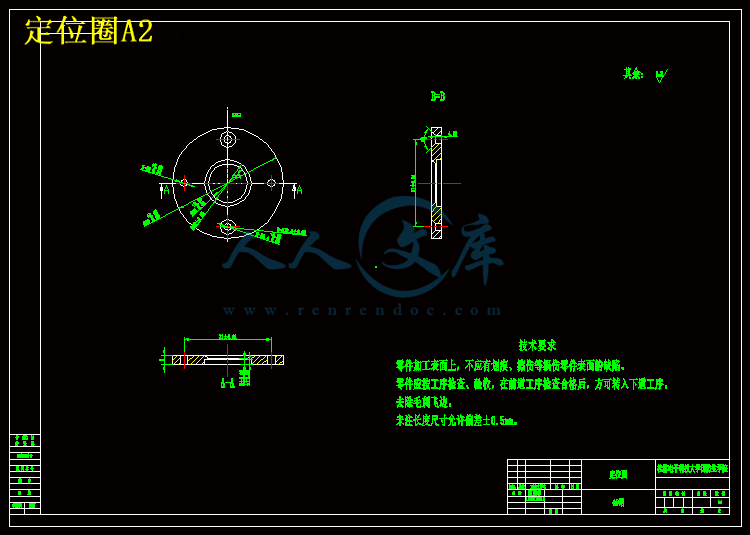
定位圈A2.exb
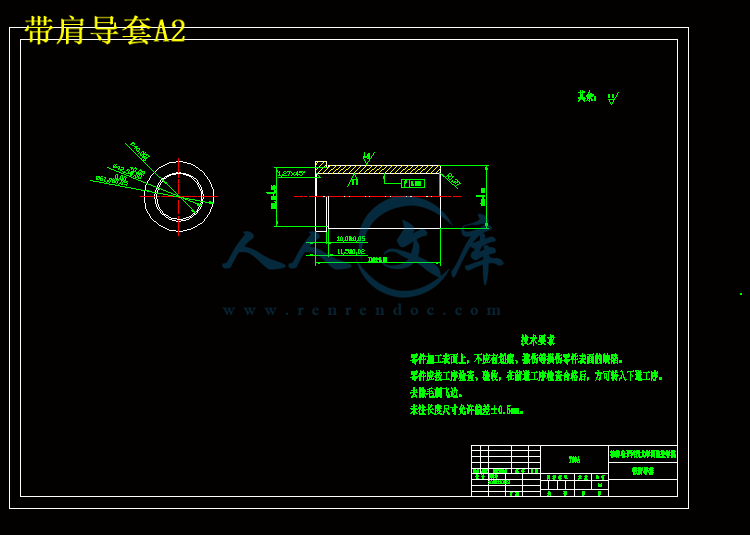
带肩导套A2.exb
应急灯塑件图A1.exb
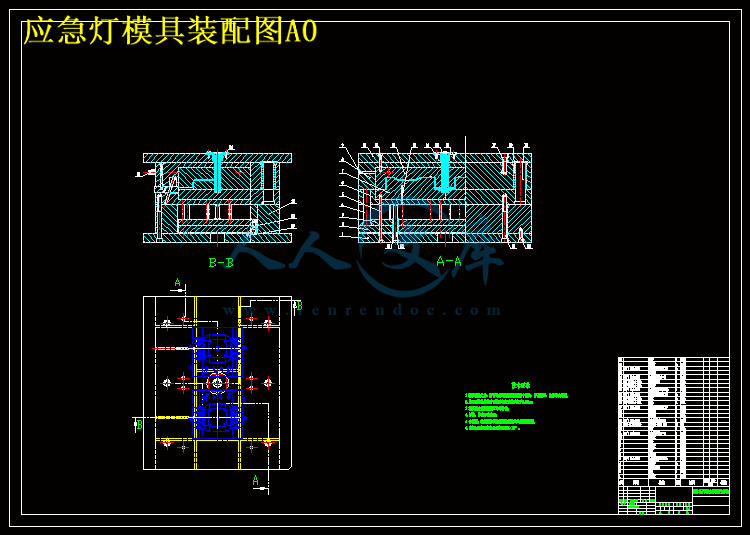
应急灯模具装配图A0.exb
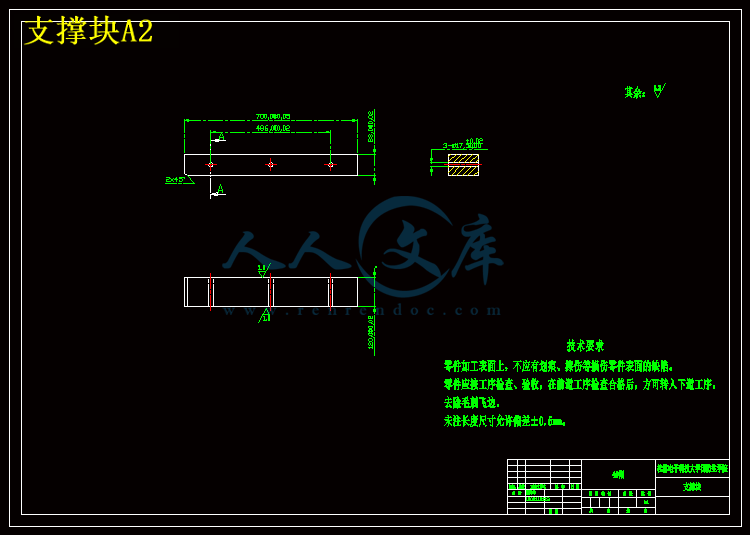
支撑块A2.exb
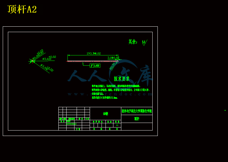
顶杆A2.exb
型腔板A1.dwg
复位杆A2.dwg
定位圈A2.dwg
带肩导套A2.dwg
应急灯塑件图A1.dwg
应急灯模具装配图A0.dwg
支撑块A2.dwg
顶杆A2.dwg
压缩包内文档预览:
预览图 预览图
编号:10118841    类型:共享资源    大小:7.84MB    格式:RAR    上传时间:2018-05-23 上传人:俊****计 IP属地:江苏
40
积分
关 键 词:
应急灯 外壳 注塑 模具设计 cad 图纸 以及 说明书 仿单
资源描述:

摘  要


本论文主要研究的是应急灯外壳注塑模具的设计方法。本文首先介绍了选题的依据以及选这个课题的意义,并简单介绍了注塑模具的发展现状。然后分析了应急灯外壳制件的工艺特点,包括结构工艺性、成型特性与条件、材料性能等,并选定了成型设备。接着述说了应急灯外壳注塑模的分型面选择、模具基本结构及模架的选定及型腔数目的选定及布置,重点论述了成型零件、浇注系统、、脱模机构、合模导向机构以及冷却系统的设计。而后选定标准模架和模具材料,并校核注射机的相关工艺参数,如最大注射量、注塑压力等。最后阐述模具的工作原理,以及对安装运行过程中可能出现的问题予以总结、分析,并给于了对应的解决方法。

本文论述的应急灯外壳注塑模具采用两板式结构,采用一模两腔的型腔布置,最后通过推板将制件推出。在设计模具的时候,需用到SoliWorks软件进行模拟,以确定型芯型腔及浇口位。此次应急灯外壳注塑模具的设计各项参数必须来源可靠、选择准确、计算无误,其中最大注射量及注射压力是计算的关键。在工艺性上保证不影响操作的同时尽量做到了加工操作简单、方便。

本设计是在传统的应急灯上进行了创新,设计采用最领先技术LED显示,并把电池装在灯内部,外部也更美观。外壳的尺寸大小适中,模架也较好的选择,模具整体不大,采用整体安装。


关键词:应急灯外壳;注塑模;两板模;浇注系统;脱模机构


Abstract


The designing methods of injection mould of the Emergency light shell are mainly introduced in this paper. This paper introduces the topic basis and the significance of choosing thistopic, and briefly introduces the development status of injection mold.And then analyzes the process characteristics of emergency lamp shellparts, including the structure, characteristics and conditions of moldingprocess, material properties, and select the molding equipment.Then tell the type emergency lamp shell injection mold, mold surfacestructure and mold base selection and the number of cavities selection andlayout, emphasis, gating system, forming parts, demoulding mechanism,clamping mechanism and the cooling system design.Finally the selected standard mold and mold material, and process parameters of injection machine check, such as the maximum injection volume, injection pressure etc.. The working principle of the die, as well as to the possible problems in the process of installation and operation are summarized, analysis, and give the corresponding solutions.

Shell of emergency lamp injection mold in this paper adopts two plate structure, the layout of the cavity of a mould with two cavities, the push platewill work out.In the design of mold, use the SoliWorks software to simulate, in order to determine the core and cavity and runner position.Must choose accurate, reliable, accurate calculation of design parameters of the emergency lamp shell injection mold, the largest injection quantityand injection pressure is the key.In the process that does not affect the operation at the same time as far as possible the process has the advantages of simple operation, convenient.

This design is the innovation in the emergency lights on the traditionaldesign, using the most advanced technology of LED display, and the battery installed in the light of internal, external and more beautiful.Moderate size of shell mold, is the better choice, overall not die, the wholeinstallation.

Keyword: Emergency light shell;Injection mould;Threepence mould;Gating system;Moulding mechanism ; Space parting institutions


目    录


引言 1

第1章  应急灯外壳工艺性分析 4

1.1 材料性能 4

1.2 成型特性和条件 4

1.3 结构工艺性 4

1.4 产品几何形状分析 5

1.5 应急灯外壳注塑工艺参数的确定 9

1.6 初选注射机的型号和规格 9

第2章  应急灯外壳注塑模具的结构设计 11

2.1 分型面的选择 11

2.2 确定模具基本结构及模架的选定 12

2.3 确定型腔的数量和布局 12

2.4浇注系统设计 13

2.4.1主流道设计 13

2.4.2 分流道截面设计及布局 14

2.4.3 浇口设计及位置选择 15

2.4.4 浇口套的设计 16

2.5 注塑模成型零部件设计 17

2.5.1 成型零部件尺寸分析 17

2.5.2塑件收缩率的影响 17

2.5.3型腔、型芯结构设计 18

2.5.4 成型零件工作尺寸计算 20

2.6 合模导向机构设计 20

2.7 脱模、推出机构设计 21

2.7.1 推出机构的组成 21

2.7.2 推出机构的分类 21

2.7.3 推出机构的设计原则 21

2.8冷却系统设计 23

2.9 模架及模具材料的选择 24

第3章  注射机相关参数校核 25

3.1 最大注射量的校核 25

3.2 注射压力校核 26

3.3 锁模力校核 26

3.4 模具厚度的校核 26

3.5 成型零部件强度校核计算 27

第4章  模具的工作原理及安装、调试 28

4.1 模具的工作原理 28

4.2 模具的安装 29

4.3 试模 29

结论 31

谢  辞 32

参考文献 33


引言

1.选题的依据及意义

随着现代制造技术及高新技术的迅速发展、计算机科技的应用,在工业中模具将要变成生产各种产品不可缺少的重要工艺装备。尤其是在塑料产品的制造和生产过程中,应用塑料模具相当广泛,在各类模具中的重要程度也越来越突显,成为一系列模具设计、制造与研究中最具有表现意义的模具之一。随着注塑模具不断成为生产塑料制造品的主要手段,且不断发展成为最有前景的模具之一。注射成型是现在市场上最具前景、最常用的塑料成型手段之一,因此注塑模具作为塑料模的一种,它将具有相当大的市场需求量。因此我选应急灯注塑模具设计作为我毕业设计选择的课题。

本课题知识点与涉及的知识面较多,应用性强与,如模具设计、三维造型、注塑成型、二维三维软件的应用以及运动仿真。

内容简介:
编号: 毕业设计(论文)任务书题 目:应急灯外壳注塑模具设计学 院: 专 业:学生姓名: 学 号: 指导教师单位: 姓 名: 职 称: 题 目 类 型 : 理 论 研 究 实 验 研 究 工 程 设 计 工 程 技 术 研 究 软 件 开 发2013 年 12 月 9 日一、 毕业设计(论文)的内容1.塑件的分析 2.塑件材料的选用与性能分析(特性及成型工艺参数) 3.拟定模具的结构形式(型腔的数目及排布)4.浇注系统的设计 5.分流道的设计 6.浇口的设计 7.冷料穴和拉料杆的设计 8.成型零件的设计 9.导向机构的设计10.脱模推出机构的设计 11.侧向分型与抽心机构设计 12.排气系统的设计 13.温度调节系统的设计 14.限位钉设计.二、 毕业设计(论文)的要求与数据1.外型尺寸及精度 2.使用环境 3.收缩率 4.外观要求 5.塑料壁厚 6.ABS 主要技术指标及工艺参数 7.设计中的计算 8.安装尺寸的校核三、毕业设计(论文)应完成的工作1、完成二万字左右的毕业设计说明书(论文) ;在毕业设计说明书(论文)中必须包括详细的 300-500 个单词的英文摘要;2、独立完成与课题相关,不少于四万字符的指定英文资料翻译(附英文原文) ;3、用 AutoCAD 软件绘制系统设计图纸,模具的装配图,零件图和塑件图打印图纸折合 0 号图纸 1 张以上。对于机电结合类课题,必须完成绘图工作量折合 A0 图纸 1 张以上,其中必须包含两张 A3 以上的计算机绘图图纸;四、应收集的资料及主要参考文献1 大连理工大学工程画教研室编.机械制图M.北京:高等教育出版社,2003.2 叶久新,王群主编.塑料成型工艺及模具设计M.北京:机械工业出版社,2007.3 屈华昌主编.塑料成型工艺与模具设计M.北京:机械工业出版社,1996.4 翁其金塑料模塑成型技术M北京:机械工业出版社,2000.2 5 模具实用技术丛书编委会模具实用技术注塑模具设计制造与应用实例M北京:机械工业出版社 2002.26 陈世煜 陈可娟塑料注塑成型模具设计M北京:国防工业出版社,2007.9 7 唐志玉大型注塑模具设计原理与应用M北京:化学工业出版社,2002.18 王树勋 朱亚林注塑模具设计M广州:华南理工大学出版社,2005.59 模具设计编委会塑料模具技术手册M北京:机械工业出版社,2002.510 李学锋塑料模设计及制造M北京:机械工业出版社,2002.611 王敏杰 宋满仓模具制造技术M北京:电子工业出版社, 200412 田福祥五板式推板推件高压聚乙烯堵头注塑模J塑料科技200713 朱光.塑料注塑模中小型模架及其技术条件M.北京:清华大学出版社,2003.114 cunha,L,et.al.,performance of chromium nitride and titanium nitride coatings during platics injection moulding. Surface and coating Technology,2002.153(2-3):p.160-165.五、试验、测试、试制加工所需主要仪器设备及条件计算机(autoCAD, 及 pro/E,protel 软件),任务下达时间:2013 年 12 月 9 日毕业设计开始与完成时间:2013 年 12 月 17 日至 2014 年 05 月 8 日组织实施单位:教研室主任意见:签字: 2013 年 12 月 14 日院领导小组意见:签字: 2013 年 12 月 16 日编号: 毕业设计(论文)开题报告题 目: 应急灯外壳注塑模具设计院 (系): 专 业: 学生姓名: 学 号: 指导教师单位: 姓 名: 职 称: 题 目 类 型 : 理 论 研 究 实 验 研 究 工 程 设 计 工 程 技 术 研 究 软 件 开 发2013 年 12 月 23 日- 0 -1毕业设计的主要内容、重点和难点等毕业设计的主要内容:毕业设计课题为时尚艺术塑料板凳注塑模具设计。近几年,我国塑料模具工业有了很大的发展,塑料制品在我们的日常生活中扮演着越来越重要的角色,其种类也越来越多,制造加工也越来越精致美观。在未来的模具市场中,塑料模具发展的速度将高于其它模具,在模具行业中的比例将逐步提高。并且随着注塑模具技术的发展,在工程机械和工业机械、电子、汽车、家电、玩具等产品中,60%以上的零部件,可以依靠模具成型。 随着国内经济发展,居民生活水平的提高,塑料板凳已经成为日常生活中常备的用品。塑料板凳也出现了多种样式,其中更多的板凳以其精美的外观,低廉的价格,以及耐用的特点而受到企业和广大消费者的欢迎。塑料板凳虽然看似简单,但是其注塑模具的设计制造所涉及的知识面和知识点比较多,能比较全面的反应一些注塑模具设计的特点。本课题应用性强,知识面覆盖较广,并且来自生活,所以容易激发我学习研究的兴趣,所以选择了这个课题,其主要内容如下:1、参观调研,查阅资料。到模具制造相关企业调研,了解模具设计、生产、制造及加工情况。结合本次毕设课题,查阅模具相关资料;2、撰写开题报告;3、通过对产品的性能分析,完成相关的模具结构与零件设计;4、设计的模具结构要求完整、合理;5、合理选择尺寸、公差、表面粗糙度和制件材料,绘制的产品图样完整;6、认真分析制件图,确定模具型腔、模具结构、分型面和进料口形式,计算含收 缩率的相关尺寸和模具的强度和刚度;7、翻译专业外语文献。8、撰写毕业设计(论文)说明书;9、绘制模具总装图、零件图;毕业设计的重点难点:1、脱模推出机构和侧抽芯机构的设计;2、塑件的合理性设计及结构工艺性分析;3、材料选择,收缩率计算。模具强度及刚度分析;4、塑件壁厚成型工艺考虑及保证塑件的外观要求;5、模具型腔数的确定,模具结构、分型面和进料口形式的选择;6、保证塑件成型时无变形,注出的制件表面光滑,无气泡和其它缺陷,无飞边或少飞边。7、绘制模具总装图、零件图及尺寸标注。- 1 -2准备情况(查阅过的文献资料及调研情况、现有设备、实验条件等)1、模具技术的现状模具是汽车、电子、电器、航空、仪表、轻工、塑料、日用品等工业部门极其重要的工艺装备。没有模具、就没有高质量的产品。模具不是一般的工艺装备,而是技术密集型的产品,工业发达国家把模具作为机械制造方面的高科技产品来对待。他们认为:“模具是发展工业的一把钥匙;模具是一个企业的心脏;模具是富裕社会的一种动力” 。 近年来,我国塑料模具业发展相当快,目前,塑料模具在整个模具行业中约占30%左右,而在整个塑料模具市场以注塑模具需求量最大。随着模具制造行业的发展,许多企业开始追求提高产品质量及生产效率,缩短设计周期及制造周期,降低生产成本,最大限度地提高模具制造业的应变能力等目标。新兴的模具 CAD 技术很大程度上实现了企业的愿望。近年来,CAD 技术的应用越来越普遍和深入, 大大缩短了模具设计周期, 提高了制模质量和复杂模具的制造能力。 目前,美国、日本、德国等工业发达国家模具工业的产值均已超过机床工业总产值。美国模具年产值已超过 1O0 亿美元;日本从 1957 年到 1984 年二十七年间, 模具工业增长 100 倍;1987 年台湾地区模具出口达一亿二千万美元。香港的模具年产值为 30 亿港币,我国的模具年产值为人民币 3O 亿元。 从整体来看,中国塑料模具无论是在数量上,还是在质量、技术和能力等方面都有了很多进步,但与国民经济发展的需求、世界先进水平相比,差距仍然很大。主要缺陷明显的表现在精度不高,技术含量低、复杂程度低等缺点。严重的阻碍着国内模具业的发展。一些大型、精密、复杂、长寿命的中高档塑料模具每年仍需大量进口。在总量供不应求的同时,一些低档塑料模具却供过于求,市场竞争激烈,还有一些技术含量不太高的中档塑料模具也有供过于求的趋势。因此中国塑料模具行业和国外先进水平相比,主要存在一下问题:发展不平衡,产品总体水平较低;工艺装备落后,组织协调能力差;大多数企业开发能力弱,创新能力明显不足;供需矛盾短期难以缓解;体制和人才问题的解决尚需时日。这些都严重的阻碍着国内电子业的发展。设计出好的产品却无法做出是我模具业的最大不足。因此,注重科技含量,借助了国外的先进理论技术则尤为重要。大型化、高精密度、节能复合型模具将是未来注塑模具的发展方向。随着国际化,市场竞争越来越激烈,短周期、高质量、长寿命的高档塑料模具也会加大研制与开发。同时,注塑模具将与并行工程、精益生产、敏捷制造等多种生产模式密切结合,最终使塑料模具行业发生重大变革。- 2 -2、注塑模简介注塑成型又称注塑模具,是热塑性塑料制件的一种主要成型方法,并且能够成功地将某些热固性塑料注塑成型。注塑成型可成型各种形状的塑料制品,其优点包括成型周期短,能一次成型外形复杂、尺寸精密、带有嵌件的制品,且生产效率高易于实现自动化,因而广泛应用在塑料制品生产当中。3、注塑成型原理及特点塑料的注塑成型过程,就是借助螺杆或柱塞的推力,将已塑化的塑料熔体以一定的压力和速度注入模具型腔内,经过冷却固化定型后开模而获得制品。因此,可以说注塑成型在塑料装配生产中具有重要地位。4、注塑成型原理注塑成型所用的模具即为注塑模(也称为注射模) ,注塑成型的原理(以螺杆式注射机为例) 。首先将颗粒或粉状的塑料加入料斗,然后输送到侧装有电加热的料筒中塑化。螺杆在料筒前端原地转动,使被加热预塑的塑料在螺杆的转动作用下通过螺旋槽输送至料筒前端的喷嘴附近。螺杆的转动使塑料进一步化,料温在剪切摩擦热的作用下进一步提高并得以均匀化。当料筒前端堆积的体对螺杆产生一定的压力时(称为螺杆的背压) ,螺杆将转动后退,直至整好的行程开关接触,从而使螺母与螺杆锁紧。具有模具一次注射量的塑料预塑和储过程结束。这时,马达带动气缸前进,与液压缸活塞相连接的螺杆以一定的速度和压力将熔料通过料筒前端的喷嘴注入温度较低的闭合模具型腔中。熔体通过喷嘴注入闭合模具腔后,必须经过一定时间的保压,熔融塑料才能冷却固化,保持模具型腔所赋予形状和尺寸。当合模机构打开时,在推出机构的作用下,即可顶出注塑成型的塑料制品。5、应急灯外壳注塑模具设计的流程:(1)思考与创新:绘制草图,确定应急灯外壳的外观形式;(2)实践操作:通过 Pro-e 软件画出应急灯外壳的三维模型;(3)用 Pro-e 做出内部的结构,实现外观要求;(4)将 Pro-e 做的图导入 AutoCAD 中;(5)修改结构图。6、注射模具的设计过程(1)对塑料零件的材料、形状和功能进行分析(2)确定型腔的数目确定型腔的数目条件有:最大注射量、锁模力、产品的精度要求和经济性等。- 3 -(3)选择分型面分型面的选择应以模具结构简单、分型容易,且不破坏已成型的塑件为原则。(4)型腔的布置方案型腔的布置应采用平衡式排列,以保证各型腔平衡进料。型腔的布置还要注意与冷却管道、推杆布置的协调问题。(5)确定浇注系统浇注系统包括主流道、分流道、浇口和冷料穴。浇注系统的设计应根据模具的类型、型腔的数目及布置方式、塑件的原料及尺寸等确定。(6)确定脱模方式脱模方式的设计应根据塑件留在模具的部分而同。由于注射机的推出顶杆在动模部分,所以,脱模推出机构一般都设计在模具的动模部分。因此,应设计成使塑件能留在动模部分。设计中,除了将较长的型芯安排在动模部分以外,还常设计拉料杆,强制塑件留在动模部分。但也有些塑件的结构要求塑件在分型时,留在定模部分,在定模一侧设计出推出装置。推出机构的设计也应根据塑件的不同结构设计出不同的形式,有推杆、推管和推板等结构。(7)确定调温系统结构模具的调温系统主要由塑料种类决定。模具的大小、塑件的物理性能、外观和尺寸精度都对模具的调温系统有影响。(8)确定凹模和型心的固定方式当凹模或型心采用镶块结构时,应合理地划分铁块并同时考虑镶块的强度、可加工性及安装固定。(9)确定排气尺寸一般注射模的排气可以利用模具分型面和推杆与模具的间隙;而对于大型和高速成型的注射模,必须设计相应的排气装置。(10)确定注射模的主要尺寸根据相应的公式,计算成型零件的工作尺寸,以及决定模具型腔的侧壁厚度、动模板的厚度、拼块式型腔的型腔板的厚度及注射模的闭合高度。(11)选用标准模架根据设计、计算的注射模的主要尺寸,来选用注视模的标准模架,并尽量选择标准模具零件。(12)绘制模具的结构草图在以上工作的基础上,绘制注射模的完整的结构草图,绘制模具结构图是模具设计十分重要的工作,其步骤为先画俯视图(顺序为:画模架、型腔、冷却管道、支撑柱、推出机构) ,再画出主视图。(13)校核模具与注射机有关尺寸对所使用的注射机的参数进行校核:包括最大注射量、注射压力、锁模力及模具- 4 -的安装部分的尺寸、开模行程和推出机构的校核。(14)注射模结构设计的审查对根据上述有关注视模结构设计的各项要求设计出来的注射模,应进行注射模结构设计的初步审查,同时,也有必要对提出的要求加以确认和修改。(15)绘制模具的装配图装配图是模具装配的主要依据,因此应清楚地表明注视模的各个零件的装配关系、必要的尺寸(如外形尺寸、定位圈直径、安装尺寸、活动零件的极限尺寸等) 、序号、明细表、标题栏及技术要求。(16)绘制模具的零件图由模具装配图拆绘零件图的顺序为:先内后外,先复杂后简单,先成型零件后结构零件。(17)复核设计图样注射模具设计的最后是审核所设计的注射模,应多关注零件的加工、性能。已查阅的文献资料 1 大连理工大学工程画教研室编.机械制图M,高等教育出版社,20032 叶久新 王群主编.塑料成型工艺及模具设计M,机械工业出版社,2007.3 屈华昌主编.塑料成型工艺与模具设计.北京M:机械工业出版社,1996.4 翁其金塑料模塑成型技术M北京:机械工业出版社,2000.2 5 模具实用技术丛书编委会模具实用技术注塑模具设计制造与应用实例M北京:机械工业出版社 2002.26 陈世煜 陈可娟塑料注塑成型模具设计M北京:国防工业出版社,2007.9 7 唐志玉大型注塑模具设计原理与应用M北京:化学工业出版社,2002.18 王树勋 朱亚林注塑模具设计M广州:华南理工大学出版社,2005.59 模 具 设 计 编委会塑料模具技术手册M北京:机械工业出版社,2002.510 李 学 锋 塑 料 模 设 计 及 制 造 M北 京 : 机 械 工 业 出 版 社 , 2002.611 王敏杰 宋满仓模具制造技术M北京:电子工业出版社, 20047 12 田福祥五板式推板推件高压聚乙烯堵头注塑模J塑料科技2007(2)13 朱光.塑料注塑模中小型模架及其技术条件M。北京:清华大学出版社,2003,114 cunha,L,et.al.,performance of chromium nitride and titanium nitride coatings during platics injection moulding. Surface and coating - 5 -Technology,2002.153(2-3):p.160-165.现有设备及实验条件:计算机一台,使用软件为 Pro/Engineer5.0 及 Auto CAD2008、Moldflow insight,以上实验条件可满足本次毕业设计的要求。3、实施方案、进度实施计划及预期提交的毕业设计资料1.2013 年 12 月 17 日至 2013 年 12 月 30 日,理解消化毕设任务书要求并收集、分析、消化资料文献,根据毕设内容完成并交开题报告;2.2013 年 1 月 6 日至 2014 年 1 月 13 日,开展调研,了解塑件结构,对原材料进行分析,考虑塑件的成型工艺性、模具的总体结构的形式,并完成部分英文摘要翻译。3.2014 年 3 月 4 日至 2013 年 3 月 31 日,查阅资料,熟悉注射模的结构及有关计算,拟定模具的方案设计、总体设计及主要零件设计,拟定成型工艺过程,查阅有关手册确定适宜的工艺参数,注射机的选择及确定注射设备及型号规格;4.2014 年 4 月 1 日至 2014 年 4 月 21 日,完成设计计算任务,总体结构的设计和完成总装配图及零件图的设计;5.2014 年 4 月 22 日至 2014 年 5 月 1 日,完成设计,图纸绘制任务,工艺规程说明书的编写;6.2014 年 5 月 1 日至 2014 年 5 月 4 日,完善设计并完成论文的撰写;7.2014 年 5 月 4 日至 2014 年 5 月 8 日,修改并打印毕业论文及整理相关资料,交指导老师评阅,准备论文答辩。- 6 -指导教师意见指导教师(签字):2013 年 12 月 日开题小组意见开题小组组长(签字):2014 年 1 月 日院(系、部)意见- 7 -主管院长(系、部主任)签字:2014 年 1 月 日毕业设计(论文)中期检查表(指导教师)指导教师姓名: 填表日期: 2014 年 4 月 20 日学生学号 学生姓名 题目名称 应急灯外壳注塑模具设计已完成内容开题并做调研,进行翻译;确定其方案设计;完成结构设计;绘制结构草图;完成相关计算;完成英文翻译;绘制装配图;绘制零件图;撰写论文;完成毕业设计。检查日期:2014-4-20完成情况 全部完成按进度完成滞后进度安排存在困难解决办法查阅相关资料,并且与指导老师和同学们一起讨论解决方案。预期成绩 优 秀 良 好 中 等 及 格 不及格建议教师签名:教务处实践教学科制表说明:1、本表由检查毕业设计的指导教师如实填写;2、此表要放入毕业设计(论文)档案袋中;3、各院(系)分类汇总后报教务处实践教学科备案Journal of Materials Processing Technology 171 (2006) 259267 Design and thermal analysis of plastic injection mould S.H. Tang , Y .M. Kong, S.M. Sapuan, R. Samin, S. Sulaiman Department of Mechanical and Manufacturing Engineering, Universiti Putra Malaysia, 43400 Serdang, Selangor, Malaysia Received 3 September 2004; accepted 21 June 2005 Abstract This paper presents the design of a plastic injection mould for producing warpage testing specimen and performing thermal analysis for the mould to access on the effect of thermal residual stress in the mould. The technique, theory, methods as well as consideration needed in designing of plastic injection mould are presented. Design of mould was carried out using commercial computer aided design software Unigraphics, Version 13.0. The model for thermal residual stress analysis due to uneven cooling of the specimen was developed and solved using a commercial nite element analysis software called LUSAS Analyst, Version 13.5. The software provides contour plot of temperature distribution for the model and also temperature variation through the plastic injection molding cycle by plotting time response curves. The results show that shrinkage is likely to occur in the region near the cooling channels as compared to other regions. This uneven cooling effect at different regions of mould contributed to warpage. 2005 Elsevier B.V . All rights reserved. Keywords: Plastic Injection mould; Design; Thermal analysis 1. Introduction Plastic industry is one of the worlds fastest growing industries, ranked as one of the few billion-dollar industries. Almost every product that is used in daily life involves the usage of plastic and most of these products can be produced by plastic injection molding method 1. Plastic injection molding process is well known as the manufacturing process to create products with various shapes and complex geometry at low cost 2. The plastic injection molding process is a cyclic process. There are four signicant stages in the process. These stages are lling, packing, cooling and ejection. The plastic injec- tion molding process begins with feeding the resin and the appropriate additives from the hopper to the heating/injection system of the injection plastic injection molding machine 3. This is the “lling stage” in which the mould cavity is lled with hot polymer melt at injection temperature. After the cav- ity is lled, in the “packing stage”, additional polymer melt is packed into the cavity at a higher pressure to compensate the expected shrinkage as the polymer solidies. This is followed Corresponding author. E-mail address: saihong.my (S.H. Tang). by “cooling stage” where the mould is cooled until the part is sufciently rigid to be ejected. The last step is the “ejection stage” in which the mould is opened and the part is ejected, after which the mould is closed again to begin the next cycle 4. The design and manufacture of injection molded poly- meric parts with desired properties is a costly process domi- nated by empiricism, including the repeated modication of actual tooling. Among the task of mould design, designing the mould specic supplementary geometry, usually on the core side, is quite complicated by the inclusion of projection and depression 5. In order to design a mould, many important designing factors must be taken into consideration. These factors are mould size, number of cavity, cavity layouts, runner systems, gating systems, shrinkage and ejection system 6. In thermal analysis of the mould, the main objective is to analyze the effect of thermal residual stress or molded-in stresses on product dimension. Thermally induced stresses develop principally during the cooling stage of an injection molded part, mainly as a consequence of its low thermal conductivity and the difference in temperature between the molten resin and the mould. An uneven temperature eld exists around product cavity during cooling 7. 0924-0136/$ see front matter 2005 Elsevier B.V . All rights reserved. doi:10.1016/j.jmatprotec.2005.06.075260 S.H. Tang et al. / Journal of Materials Processing Technology 171 (2006) 259267 During cooling, location near the cooling channel experi- ences more cooling than location far away from the cooling channel. This different temperature causes the material to experience differential shrinkage causing thermal stresses. Signicant thermal stress can cause warpage problem. There- fore, it is important to simulate the thermal residual stress eld of the injection-molded part during the cooling stage 8.By understanding the characteristics of thermal stress distribu- tion, deformation caused by the thermal residual stress can be predicted. In this paper the design of a plastic injection mould for producing warpage testing specimen and for performing ther- mal analysis for the mould to access on the effect of thermal residual stress in the mould is presented. 2. Methodology 2.1. Design of warpage testing specimen This section illustrates the design of the warpage testing specimen to be used in plastic injection mould. It is clear that warpage is the main problem that exists in product with thin shell feature. Therefore, the main purpose of the prod- uct development is to design a plastic part for determining the effective factors in the warpage problem of an injection- moulded part with a thin shell. The warpage testing specimen is developed from thin shell plastics. The overall dimensions of the specimen were 120 mm in length, 50 mm in width and 1 mm in thickness. The material used for producing the warpage testing specimen was acrylonitrile butadiene stylene (ABS) and the injection temperature, time and pressure were 210 C, 3 s and 60 MPa, respectively. Fig. 1 shows the warpage testing specimen pro- duced. 2.2. Design of plastic injection mould for warpage testing specimen This section describes the design aspects and other consid- erations involved in designing the mould to produce warpage testing specimen. The material used for producing the plastic Fig. 1. Warpage testing specimen produced. injection mould for warpage testing specimen was AISI 1050 carbon steel. Four design concepts had been considered in designing of the mould including: i. Three-plate mould (Concept 1) having two parting line with single cavity. Not applicable due to high cost. ii. Two-plate mould (Concept 2) having one parting line with single cavity without gating system. Not applicable due to low production quantity per injection. iii. Two-plate mould (Concept 3) having one parting line with double cavities with gating and ejection system. Not applicable as ejector pins might damage the product as the product is too thin. iv. Two-plate mould (Concept 4) having one parting line with double cavities with gating system, only used sprue puller act as ejector to avoid product damage during ejection. In designing of the mould for the warpage testing spec- imen, the fourth design concept had been applied. Various design considerations had been applied in the design. Firstly, the mould was designed based on the platen dimen- sion of the plastic injection machine used (BOY 22D). There is a limitation of the machine, which is the maximum area of machine platen is given by the distance between two tie bars. The distance between tie bars of the machine is 254 mm. Therefore, the maximum width of the mould plate should not exceed this distance. Furthermore, 4 mm space had been reserved between the two tie bars and the mould for mould setting-up and handling purposes. This gives the nal max- imum width of the mould as 250 mm. The standard mould base with 250 mm 250 mm is employed. The mould base is tted to the machine using Matex clamp at the upper right and lower left corner of the mould base or mould platen. Dimen- sions of other related mould plates are shown in Table 1. The mould had been designed with clamping pressure having clamping force higher than the internal cavity force (reaction force) to avoid ashing from happening. Based on the dimensions provided by standard mould set, the width and the height of the core plate are 200 and 250 mm, respectively. These dimensions enabled design of two cavities on core plate to be placed horizontally as there is enough space while the cavity plate is left empty and it is only xed with sprue bushing for the purpose of feeding molten plastics. Therefore, it is only one standard parting line was designed at Table 1 Mould plates dimensions. Components Size (mm) width height thickness Top clamping plate 250 250 25 Cavity plate 200 250 40 Core plate 200 250 40 Side plate/support plate 37 250 70 Ejector-retainer plate 120 250 15 Ejector plate 120 250 20 Bottom clamping plate 250 250 25S.H. Tang et al. / Journal of Materials Processing Technology 171 (2006) 259267 261 the surface of the product. The product and the runner were released in a plane through the parting line during mould opening. Standard or side gate was designed for this mould. The gate is located between the runner and the product. The bottom land of the gate was designed to have 20 slanting and has only 0.5 mm thickness for easy de-gating purpose. The gate was also designed to have 4 mm width and 0.5 mm thickness for the entrance of molten plastic. In the mould design, the parabolic cross section type of runner was selected as it has the advantage of simpler machin- ing in one mould half only, which is the core plate in this case. However, this type of runner has disadvantages such as more heat loss and scrap compared with circular cross section type. This might cause the molten plastic to solidify faster. This problem was reduced by designing in such a way that the runner is short and has larger diameter, which is 6 mm in diameter. It is important that the runner designed distributes material or molten plastic into cavities at the same time under the same pressure and with the same temperature. Due to this, the cavity layout had been designed in symmetrical form. Another design aspect that is taken into consideration was air vent design. The mating surface between the core plate and the cavity plate has very ne nishing in order to prevent ashing from taking place. However, this can cause air to trap in the cavity when the mould is closed and cause short shot or incomplete part. Sufcient air vent was designed to ensure that air trap can be released to avoid incomplete part from occurring. The cooling system was drilled along the length of the cavities and was located horizontally to the mould to allow even cooling. These cooling channels were drilled on both cavity and core plates. The cooling channels provided suf- cient cooling of the mould in the case of turbulent ow. Fig. 2 shows cavity layout with air vents and cooling channels on core plate. In this mould design, the ejection system only consists of the ejector retainer plate, sprue puller and also the ejector Fig. 2. Cavity layout with air vents and cooling channels. plate. The sprue puller located at the center of core plate not only functions as the puller to hold the product in position when the mould is opened but it also acts as ejector to push the product out of the mould during ejection stage. No addi- tional ejector is used or located at product cavities because the product produced is very thin, i.e. 1 mm. Additional ejec- tor in the product cavity area might create hole and damage to the product during ejection. Finally, enough tolerance of dimensions is given consid- eration to compensate for shrinkage of materials. Fig. 3 shows 3D solid modeling as well as the wireframe modeling of the mould developed using Unigraphics. 3. Results and discussion 3.1. Results of product production and modication From the mould designed and fabricated, the warpage testing specimens produced have some defects during trial run. The defects are short shot, ashing and warpage. The short shot is subsequently eliminated by milling of additional air vents at corners of the cavities to allow air trapped to Fig. 3. 3D solid modeling and wireframe modeling of the mould.262 S.H. Tang et al. / Journal of Materials Processing Technology 171 (2006) 259267 Fig. 4. Extra air vents to avoid short shot. escape. Meanwhile, ashing was reduced by reducing the packing pressure of the machine. Warpage can be controlled by controlling various parameters such as the injection time, injection temperature and melting temperature. After these modications, the mould produced high qual- ity warpage testing specimen with low cost and required little nishing by de-gating. Fig. 4 shows modications of the mould, which is machining of extra air vents that can eliminate short shot. 3.2. Detail analysis of mould and product After the mould and products were developed, the analysis of mould and the product was carried out. In the plastic injec- tion moulding process, molten ABS at 210 C is injected into the mould through the sprue bushing on the cavity plate and directed into the product cavity. After cooling takes place, the product is formed. One cycle of the product takes about 35 s including 20 s of cooling time. The material used for producing warpage testing speci- men was ABS and the injection temperature, time and pres- sure were 210 C, 3 s and 60 MPa respectively. The material selected for the mould was AISI 1050 carbon steel. Properties of these materials were important in determin- ing temperature distribution in the mould carried out using nite element analysis. Table 2 shows the properties for ABS and AISI 1050 carbon steel. The critical part of analysis for mould is on the cavity and core plate because these are the place where the product is formed. Therefore, thermal analysis to study the temperature Fig. 5. Model for thermal analysis. distribution and temperature at through different times are performed using commercial nite element analysis software called LUSAS Analyst, Version 13.5. A two-dimensional (2D) thermal analysis is carried out for to study the effect of thermal residual stress on the mould at different regions. Due to symmetry, the thermal analysis was performed by modeling only the top half of the vertical cross section or side view of both the cavity and core plate that were clamped together during injection. Fig. 5 shows the model of thermal analysis analyzed with irregular meshing. Modeling for the model also involves assigning properties and process or cycle time to the model. This allowed the nite element solver to analyze the mould modeled and plot time response graphs to show temperature variation over a certain duration and at different regions. For the product analysis, a two dimensional tensile stress analysis was carried using LUSAS Analyst, Version 13.5. Basically the product was loaded in tension on one end while the other end is clamped. Load increments were applied until the model reaches plasticity. Fig. 6 shows loaded model of the analysis. 3.3. Result and discussion for mould and product analysis For mould analysis, the thermal distribution at different time intervals was observed. Fig. 7 shows the 2D analysis Table 2 Material properties for mould and product Carbon Steel (AISI 1050), mould ABS Polymer, product Density, 7860 kg/m 3 Density, 1050 kg/m 3 Youngs modulus, E 208 GPa Youngs modulus, E 2.519 GPa Poissons ratio, 0.297 Poissons ratio, 0.4 Yield strength, S Y 365.4 MPa Yield strength, S Y 65 MPa Tensile strength, S UTS 636 MPa Thermal expansion, 65 10 6 K 1 Thermal expansion, 11.65 10 6 K 1 Conductivity, k 0.135 W/(m K) Conductivity, k 49.4 W/(m K) Specic heat, c 1250 J/(kg K) Specic heat, c 477 J/(kg K)S.H. Tang et al. / Journal of Materials Processing Technology 171 (2006) 259267 263 Fig. 6. Loaded model for analysis of product. contour plots of thermal or heat distribution at different time intervals in one complete cycle of plastic injection molding. For the 2D analysis of the mould, time response graphs are plotted to analyze the effect of thermal residual stress on the products. Fig. 8 shows nodes selected for plotting time response graphs. Figs. 917 show temperature distribution curves for dif- ferent nodes as indicated in Fig. 8. From the temperature distribution graphs plotted in Figs. 917, it is clear that every node selected for the graph plotted experiencing increased in temperature, i.e. from the ambient temperature to a certain temperature higher than the ambient temperature and then remained constant at this temperature for a certain period of time. This increase in tem- perature was caused by the injection of molten plastic into the cavity of the product. After a certain period of time, the temperature is then further increased to achieve the highest temperature and remained constant at that temperature. Increase in temper- ature was due to packing stages that involved high pressure, Fig. 7. Contour plots of heat distribution at different time intervals.264 S.H. Tang et al. / Journal of Materials Processing Technology 171 (2006) 259267 Fig. 8. Selected nodals near product region for time response graph plots. Fig. 9. Temperature distribution graph for Node 284. Fig. 10. Temperature dist
温馨提示:
1: 本站所有资源如无特殊说明,都需要本地电脑安装OFFICE2007和PDF阅读器。图纸软件为CAD,CAXA,PROE,UG,SolidWorks等.压缩文件请下载最新的WinRAR软件解压。
2: 本站的文档不包含任何第三方提供的附件图纸等,如果需要附件,请联系上传者。文件的所有权益归上传用户所有。
3.本站RAR压缩包中若带图纸,网页内容里面会有图纸预览,若没有图纸预览就没有图纸。
4. 未经权益所有人同意不得将文件中的内容挪作商业或盈利用途。
5. 人人文库网仅提供信息存储空间,仅对用户上传内容的表现方式做保护处理,对用户上传分享的文档内容本身不做任何修改或编辑,并不能对任何下载内容负责。
6. 下载文件中如有侵权或不适当内容,请与我们联系,我们立即纠正。
7. 本站不保证下载资源的准确性、安全性和完整性, 同时也不承担用户因使用这些下载资源对自己和他人造成任何形式的伤害或损失。
提示  人人文库网所有资源均是用户自行上传分享,仅供网友学习交流,未经上传用户书面授权,请勿作他用。
关于本文
本文标题:应急灯外壳注塑模具设计【8张CAD图纸和说明书】
链接地址:https://www.renrendoc.com/p-10118841.html

官方联系方式

2:不支持迅雷下载,请使用浏览器下载   
3:不支持QQ浏览器下载,请用其他浏览器   
4:下载后的文档和图纸-无水印   
5:文档经过压缩,下载后原文更清晰   
关于我们 - 网站声明 - 网站地图 - 资源地图 - 友情链接 - 网站客服 - 联系我们

网站客服QQ:2881952447     

copyright@ 2020-2024  renrendoc.com 人人文库版权所有   联系电话:400-852-1180

备案号:蜀ICP备2022000484号-2       经营许可证: 川B2-20220663       公网安备川公网安备: 51019002004831号

本站为文档C2C交易模式,即用户上传的文档直接被用户下载,本站只是中间服务平台,本站所有文档下载所得的收益归上传人(含作者)所有。人人文库网仅提供信息存储空间,仅对用户上传内容的表现方式做保护处理,对上载内容本身不做任何修改或编辑。若文档所含内容侵犯了您的版权或隐私,请立即通知人人文库网,我们立即给予删除!